Buraq Turbomachinery CFD Analysis Firm: Engineering Confidence Into Rotating Equipment
Buraq is a turbomachinery CFD analysis firm that models compressors, turbines, pumps, and fans to predict performance, efficiency, and failure risk before equipment is built or modified. The company’s work spans oil and gas, power generation, and aerospace, with a strong focus on centrifugal compressor CFD analysis for surge-sensitive applications. This article explains how turbomachinery CFD analysis works step by step, why rotor-stator interaction matters, and what separates a results-driven firm from a basic simulation vendor, including practical steps for choosing a reliable CFD analysis partner and common mistakes companies make when outsourcing this work.
Quick summary: Buraq is a turbomachinery CFD analysis firm that models with Confidence compressors, turbines, pumps, and fans to predict performance, efficiency, and failure risk before equipment ever runs. This guide explains how turbomachinery CFD analysis works and what separates a results-driven engineering partner from a basic simulation vendor.
Introduction
Turbomachinery CFD analysis has become essential for anyone designing or troubleshooting rotating equipment like compressors, turbines, pumps, and fans. Buraq, a turbomachinery CFD analysis firm working across oil and gas, power generation, and aerospace sectors, builds detailed flow simulations that reveal how a machine will actually perform under real operating conditions, long before it reaches a test stand.
Rotating equipment failures are expensive and disruptive. A single unplanned compressor outage on an offshore platform or a turbine blade failure in a power plant can cost millions in lost production and repairs. Turbomachinery CFD analysis lets engineers see flow separation, pressure losses, and stress-inducing flow patterns inside a virtual model, catching design weaknesses before they become field failures.
This article explains how turbomachinery CFD analysis works in practice, what makes an engineering firm trustworthy in this space, and how companies like Buraq apply these methods to real problems, including specialized centrifugal compressor CFD analysis.
What You Receive
A Buraq CFD project isn’t just a PDF at the end. You get the full package:
Simulation files. Mesh files, case files (.cas/.dat or equivalent), and solver settings, so you or your team can rerun, extend, or audit the work without starting over.
Boundary condition documentation. Every inlet condition, material property, and heat source assumption is recorded and justified, so the setup holds up in a design review or regulatory audit.
Turbulence model justification. A clear explanation of why we chose RANS, URANS, or LES for your flow regime, instead of whatever the software defaults to.
Mesh independence study. Results across multiple refinement levels, confirming the solution isn’t just an artifact of a coarse mesh.
Validation against real data. Wherever experimental, published, or manufacturer test data exists, we compare our predictions against it directly.
Design recommendations you can act on. A ranked list of changes and their expected impact, not just contour plots to interpret on your own.
This is the level of documentation your internal engineering team needs for sign-off, and what regulatory bodies expect for FAA, EASA, or MIL-SPEC submissions. It’s also what makes results defensible months or years later, when someone asks how you got there.
How Turbomachinery CFD Analysis Works
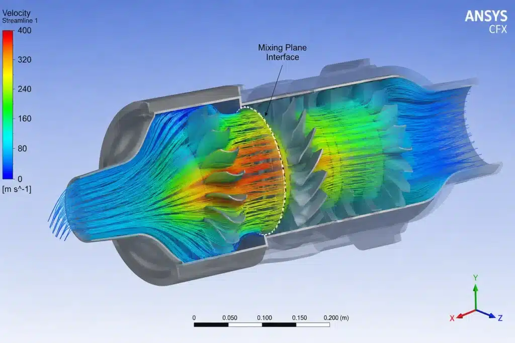
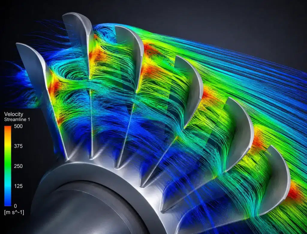
Turbomachinery CFD analysis solves the equations of fluid motion across a rotating flow path, capturing how pressure, velocity, and temperature change as fluid moves through blades, vanes, and passages. Because the geometry rotates, the simulation must account for both stationary and moving reference frames at the same time.
A typical workflow includes:
- Geometry and mesh generation – Modeling the blade passages, casing, and flow path with a mesh fine enough to resolve boundary layers near blade surfaces.
- Reference frame setup – Applying multi-reference frame or sliding mesh methods to handle the interaction between rotating and stationary components.
- Turbulence modeling – Choosing RANS, URANS, or LES models depending on whether steady-state performance or unsteady blade interactions matter most.
- Boundary condition definition – Setting inlet pressure, flow rate, rotational speed, and outlet conditions that match real operating points.
- Solving and post-processing – Simulating to convergence, then extracting performance curves, efficiency values, and flow visualizations.
Why Rotor-Stator Interaction Matters
Stationary vanes and rotating blades sit close together in most turbomachines, and the flow leaving one row directly disturbs the next. This rotor-stator interaction creates unsteady pressure pulses that a steady-state simulation misses entirely. Ignoring this effect in turbomachinery CFD analysis can underpredict vibration risk and blade fatigue, leading to designs that look fine on paper but develop cracks in service.
What Sets Buraq Apart as a Turbomachinery CFD Analysis Firm 2026
Running a CFD solver is the easy part. Interpreting results correctly and turning them into design changes that actually prevent failures is much harder. Buraq builds its turbomachinery CFD analysis practice around three pillars: component-specific depth, validation discipline, and field-failure awareness.
Component-Specific Depth
Buraq’s turbomachinery CFD analysis covers a wide range of rotating equipment:
- Centrifugal and axial compressors for oil, gas, and process industries
- Gas and steam turbines for power generation
- Centrifugal and axial pumps, including cavitation-prone designs
- Industrial fans and blowers for HVAC and process cooling
Each component type behaves differently under flow disturbances. A centrifugal compressor near its surge line behaves nothing like a pump approaching cavitation, even though both involve unstable flow separation. Firms without deep component-specific experience often apply the same generic settings across very different machines, missing problems specific to each type.
Validation Against Compressor and Turbine Performance Maps
A trustworthy turbomachinery CFD analysis firm checks its simulation results against known compressor or turbine performance maps, not just textbook values. Buraq compares predicted efficiency, pressure ratio, and mass flow against manufacturer test data whenever it’s available, catching modeling errors before they influence a design decision.
Specialized Focus: Centrifugal Compressor CFD Analysis
Centrifugal compressor CFD analysis requires careful attention to impeller-diffuser interaction, tip clearance leakage, and surge margin prediction. Small geometry changes near the impeller eye can shift the surge line significantly, and getting this wrong leads to compressors that trip offline under normal operating swings. Buraq’s centrifugal compressor CFD analysis work focuses on impeller blade loading, diffuser vane angle optimization, and stage matching for multistage compressor trains used in gas processing and pipeline applications.
Benefits and Trade-Offs of Turbomachinery CFD Analysis
| Factor Turbomachinery CFD | D Analysis Physical Testing | g Alone |
|---|---|---|
| Cost per design iteration | Low after initial model setup | High (prototype + test rig time) |
| Speed | Days to weeks per iteration | Weeks to months per build |
| Visibility into flow behavior | Full 3D pressure and velocity data | Limited to instrumented locations |
| Failure prediction | Strong for surge, stall, cavitation onset | Limited to conditions actually tested |
| Upfront investment | Higher initial setup and expertise cost | Lower entry cost, higher per-test cost |
Pros of using turbomachinery CFD analysis:
- Identifies surge, stall, and cavitation risk before hardware is built
- Tests multiple blade geometries without machining new parts
- Shortens development and troubleshooting timelines
Cons to consider:
- Requires skilled engineers to set up rotating reference frames correctly
- Unsteady simulations (URANS, LES) demand significant computing time
- Some physical validation is still necessary for critical, safety-related equipment
Practical Steps for Choosing a Turbomachinery CFD Analysis Partner
- Ask for performance map validation examples. A reliable firm should show cases where simulated efficiency and pressure ratio matched real compressor or turbine data.
- Confirm component-specific experience. If your project involves centrifugal compressors specifically, ask for examples of centrifugal compressor CFD analyses the firm has completed before.
- Clarify which turbulence and reference frame methods will be used. Steady-state RANS is faster but misses unsteady rotor-stator effects that URANS or LES can capture.
- Request a focused pilot study first. A smaller-scope analysis on one stage or component tests communication and result quality before a full project commitment.
- Review how results translate into design recommendations. Good reporting points to specific geometry changes, not just raw flow contour images.
Before committing to a full project, review a completed case study to see how Buraq structures deliverables. For budget planning, check typical CFD consulting pricing by project scope, then contact our team to discuss your specific turbomachinery application.
Expert Insight: What Separates Useful Results from Misleading Ones
Engineers who manage rotating equipment programs for years consistently say the same thing: a CFD prediction is only as good as the boundary conditions and mesh resolution behind it. Near-wall mesh density around blade surfaces strongly affects predicted losses, and getting this wrong can make an inefficient design look acceptable on screen.
A common mistake is running a single operating point and assuming it represents the whole machine’s behavior. Compressors and turbines operate across a range of flow conditions, and a design that looks strong at one point can be dangerously close to surge or stall at another. Firms that produce dependable results, including Buraq, run multiple operating points across the full performance map rather than relying on one snapshot.
For centrifugal compressor projects specifically, validating surge margin predictions against real test stand data — not just simulation trends — gives a much clearer picture of how much safety margin actually exists before a compressor trips offline.
Common Mistakes Companies Make When Outsourcing CFD Work
- Choosing a vendor based on software license alone, not engineering judgment
- Skipping validation against compressor or turbine performance maps
- Running only design-point conditions instead of the full operating range
- Overlooking rotor-stator interaction effects in vibration-sensitive designs
- Treating one simulation result as final, rather than part of an iterative design process
Avoiding these mistakes often determines whether turbomachinery CFD analysis prevents a costly failure or simply produces a report nobody acts on.
Conclusion
Turbomachinery CFD analysis has transformed how compressors, turbines, pumps, and fans are designed and troubleshot, replacing slow, expensive physical testing with detailed numerical models that reveal failure risks early. But the value of that analysis depends entirely on the firm behind it — its validation discipline, component-specific experience, and ability to turn flow data into real engineering decisions. Buraq applies these principles across oil and gas, power generation, and aerospace sectors, including specialized centrifugal compressor CFD analysis for surge-sensitive applications. For any organization evaluating a turbomachinery CFD analysis partner, prioritizing validated, component-specific experience over generic software capability will produce far better engineering outcomes.
Frequently Asked Questions
1. What does Buraq’s turbomachinery CFD analysis service include?
Buraq provides turbomachinery CFD analysis covering geometry and mesh setup, rotating reference frame modeling, turbulence selection, simulation runs, and validation against real performance data for compressors, turbines, pumps, and fans.
2. How does turbomachinery CFD analysis help prevent equipment failures?
Turbomachinery CFD analysis reveals flow separation, surge risk, cavitation onset, and unsteady pressure loads before equipment is built, allowing engineers to fix design weaknesses early instead of discovering them after a costly field failure.
3. What makes centrifugal compressor CFD analysis different from general
turbomachinery simulation? Centrifugal compressor CFD analysis focuses specifically on impeller-diffuser interaction, tip clearance leakage, and surge margin prediction, which require finer geometry detail than broader turbomachinery flow studies.
4. How accurate is turbomachinery CFD analysis compared to physical testing?
Turbomachinery CFD analysis can closely match physical test data when properly validated against performance maps, though critical or safety-related equipment usually still requires some physical confirmation testing.
5. What should companies look for when choosing a turbomachinery CFD analysis firm?
Companies should look for documented validation against performance maps, component-specific experience such as centrifugal compressor CFD analysis, clear explanations of modeling choices, and a track record of translating results into practical design changes.